Groove end butterfly valves explained: AWWA C606 grooved connection, 300 psi ratings, no-flange installation, fire protection & HVAC applications.
What Is a Groove End Butterfly Valve?
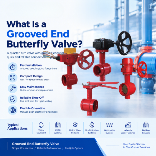
A groove end butterfly valve is a resilient-seated butterfly valve whose two pipe-connection ends are machined with circumferential grooves instead of flanges, threads or weld ends. It is joined to the pipeline by grooved mechanical couplings — two housing segments, a pressure-responsive rubber gasket and a pair of trackhead bolts — rather than by flange studs and gaskets.
Everything else is a standard soft-seated butterfly valve: ductile iron body, bonded EPDM or NBR seat, nickel-plated ductile iron disc, stainless steel stem and gear operator. The difference is entirely in the end connection. The groove profile is machined to AWWA C606, so the valve accepts the same grooved couplings used on grooved pipe.
How a Grooved Connection Works
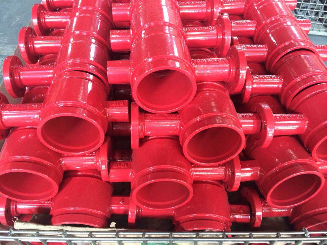
The groove end connection works on a simple mechanical principle: the coupling housing keys fit into the grooves on the valve end and the pipe end, and the housing carries the full line load while the gasket handles the seal.
- The groove: machined on valve ends to AWWA C606 dimensions. On pipe, roll grooving is preferred wherever wall thickness allows, because it cold-forms the groove without removing metal.
- The coupling: two cast housing segments that seat into both grooves and are drawn together by trackhead bolts.
- The gasket: a C-shaped, pressure-responsive elastomer seal — usually EPDM Grade E for water service up to 110°C, or nitrile where oil resistance is required. Line pressure presses the gasket lips tighter against the groove walls, so sealing actually improves as pressure rises.
- Rigid vs flexible couplings: flexible couplings absorb vibration, thermal movement and minor angular misalignment; rigid couplings hold the joint fixed for pipe hanging and support.
Because no welding, threading or flange bolting is involved, the joint is made in minutes with a wrench — no hot work permit, no flange alignment and no gasket torque pattern.
Groove End vs Wafer vs Lug vs Flanged Butterfly Valve
| End Connection |
Installation |
Space & Weight |
Maintenance |
Best For |
| Groove end |
Two couplings, wrench-only, no hot work |
Very compact, light system |
Fastest disconnect — swap a valve in minutes |
Fire protection, HVAC, retrofit, temporary lines |
| Wafer |
Clamped between two pipe flanges |
Compact valve, but flanges required |
Spreader needed to break the joint |
General water and industrial piping |
| Lug |
Bolts directly to each flange |
Compact |
One side can be removed under pressure |
Dead-end service, line isolation |
| Double flange |
Full bolted flange sets both sides |
Heavier, longer face-to-face |
Standard gasket change procedure |
Large sizes, municipal waterworks, AWWA C504 |
Key Design Features of a Groove End Butterfly Valve
- Ductile iron body with ends machined to AWWA C606 groove dimensions — epoxy coated inside and out for water service.
- Bonded EPDM seat for hot/cold water and fire systems, NBR where oil traces are present; the seat is vulcanized to the body so it cannot slip or cold-flow.
- Nickel-plated ductile iron disc with a smooth sealing surface; stainless steel disc optional for aggressive water quality.
- Blowout-proof stainless steel stem with a retaining shoulder locked under the body — the stem can never eject under line pressure.
- Gear operator with position indicator, memory stop and lockout capability; ISO 5211 top flange for electric or pneumatic actuation.
- Supervisory tamper switch (UL/FM listed) on fire protection models — the switch signals the fire alarm panel if the valve is moved from its normal position.
Pressure Ratings and Standards
Groove end butterfly valves are commonly rated 300 psi (20.7 bar) working pressure for DN50–DN300 (2″–12″), with 200–250 psi ratings on larger sizes depending on the manufacturer’s catalog. Always match the valve rating to the grooved coupling rating and the pipe schedule.
- AWWA C606 — standard for grooved and shouldered joint dimensions; this is the groove profile the valve ends must follow.
- UL / FM — required listing for valves used in fire protection sprinkler and standpipe service, including supervisory switches.
- EN 593 / API 609 — the butterfly valve design and testing standards that cover body, seat and leakage testing (EN 12266-1 Rate A for soft-seated zero visible leakage).
- Temperature limit — EPDM Grade E gaskets and seats are typically limited to about 110°C continuous in water service; verify the gasket grade, not just the valve seat.
Where Groove End Butterfly Valves Are Used
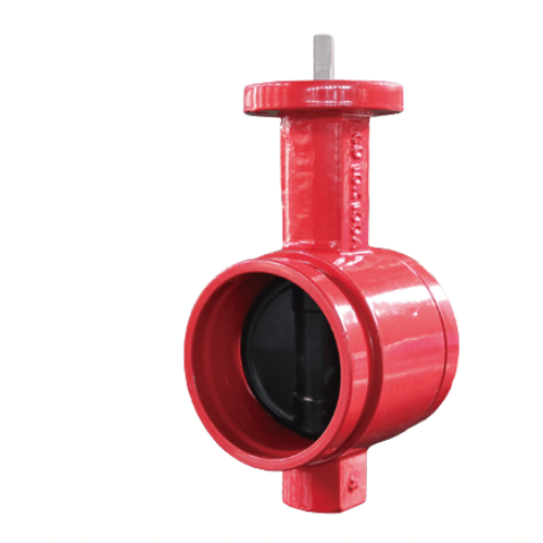
- Fire protection — sprinkler risers, pump suction and discharge headers, standpipe and zone control. The valve is normally open, locked with a supervisory tamper switch, and grooved joints are the standard connection method for fire mains.
- HVAC systems — chilled water, hot water and condenser water circuits where grooved pipe already dominates; the valve installs in minutes and can be removed without disturbing the pipe.
- Water treatment and distribution — filter skids, pump sets and plant headers where space is tight and maintenance access matters.
- Retrofit and temporary bypass lines — any site where welding or flange work would require a shutdown, hot work permit or extended downtime.
- Mining and industrial water — process water, dust suppression and slurry transfer where grooved HDPE or steel pipe is used and fast replacement is valued.
Installation Steps and Best Practices
- Verify the groove — confirm the valve end grooves and pipe grooves are cut to AWWA C606 and are free of burrs, rust and coating lumps.
- Check the gasket — match the coupling gasket grade to the media (EPDM Grade E for water, nitrile for oil-bearing water) and lubricate only with the coupling manufacturer’s approved lubricant.
- Align the valve — support the valve so its weight is not hanging on the couplings; flexible couplings allow small angular offset, rigid couplings do not.
- Tighten evenly — bring both trackhead bolts down alternately until the housing pads meet metal-to-metal. Do not over-torque; pad-to-pad contact is the torque stop.
- Test — hydrostatically test the assembled joint at the system test pressure before insulation or burying.
- Fire systems — have the supervisory switch wired and tested by a qualified technician; the valve must remain locked in its design position.
Maintenance is the grooved connection’s biggest long-term advantage: loosen two bolts, slide the couplings back, and the valve comes out for inspection without cutting the pipe or breaking flange joints.
Groove End Butterfly Valve Selection Checklist
| Item |
What to Specify |
| Size and rating |
DN50–DN300, 300 psi; confirm coupling rating matches |
| Seat and gasket |
EPDM (water) or NBR (oil traces); Grade E for hot water |
| Groove standard |
AWWA C606; confirm coupling brand compatibility |
| Operator |
Lever for DN50–DN200, gear with position indicator above |
| Fire protection |
UL/FM listing + supervisory tamper switch required |
| Actuation |
ISO 5211 top flange for electric or pneumatic retrofit |
Get a Groove End Butterfly Valve That Fits Your System
Laux Valve supplies groove end butterfly valves built on the same ductile iron, EPDM-seated platform as its wafer butterfly valve series, with AWWA C606 grooved ends, blowout-proof stems, Download the product catalog and dimensional drawings, Tell us with your size, pressure class and coupling brand for a confirmed groove compatibility check within 24 hours.


